Ray Diagram Explained: Mirrors and Lenses (with Examples)
A clear guide to the ray diagram: the principal rays, real vs virtual images, and how to draw concave mirror, convex mirror, and lens ray diagrams step by step.
A ray diagram is a scaled drawing that traces a few representative light rays through a mirror or lens to find exactly where an image forms, how big it is, whether it is upright or inverted, and whether it is real or virtual. Instead of calculating with equations alone, you draw two or three "principal" rays whose behaviour is known, and the point where they meet (or appear to meet) locates the image. This single technique works for plane mirrors, curved mirrors, and lenses, which is why ray diagrams sit at the heart of geometric optics in every physics course.
This guide explains what a ray diagram shows, the rules for the principal rays, and how to build one for the cases you meet most often — the convex mirror ray diagram, the concave mirror ray diagram, and converging and diverging lens ray diagrams — plus the optical instruments that combine them.
What a ray diagram represents
Light leaves every point of an object in all directions. A ray diagram does not try to draw all of that light; it draws only a small set of rays whose path through the optical element is predictable. Because all rays from a single object point reconverge at the same image point, just two well-chosen rays are enough to fix the image, and a third serves as a check.
Every ray diagram is built on the same skeleton:
- The principal axis, a horizontal line through the centre of the mirror or lens.
- The optical element itself — a curved mirror or a lens — drawn at the centre.
- The focal point (F), where rays parallel to the axis converge (or appear to come from) after reflection or refraction.
- For mirrors, the centre of curvature (C), twice as far from the mirror as the focal point.
- The object, usually drawn as an upright arrow, and the image the diagram locates.
The image you find is described by three properties: its type (real or virtual), its orientation (upright or inverted), and its size (magnified, diminished, or the same size).
Real images versus virtual images
The single most important distinction a ray diagram makes is between a real and a virtual image.
A real image forms where reflected or refracted rays actually cross. Light energy genuinely arrives there, so a real image can be projected onto a screen. Real images produced by a single mirror or lens are always inverted relative to the object.
A virtual image forms where rays only appear to come from. The rays diverge after leaving the element, so you extend them backwards (with dashed lines) until those extensions meet. No light actually reaches that point, so a virtual image cannot be caught on a screen — but your eye still sees it. Virtual images from a single element are always upright. The image you see in a flat bathroom mirror is a familiar virtual image.
The principal rays
The whole method rests on a handful of rays whose behaviour is fixed by the geometry of the element.
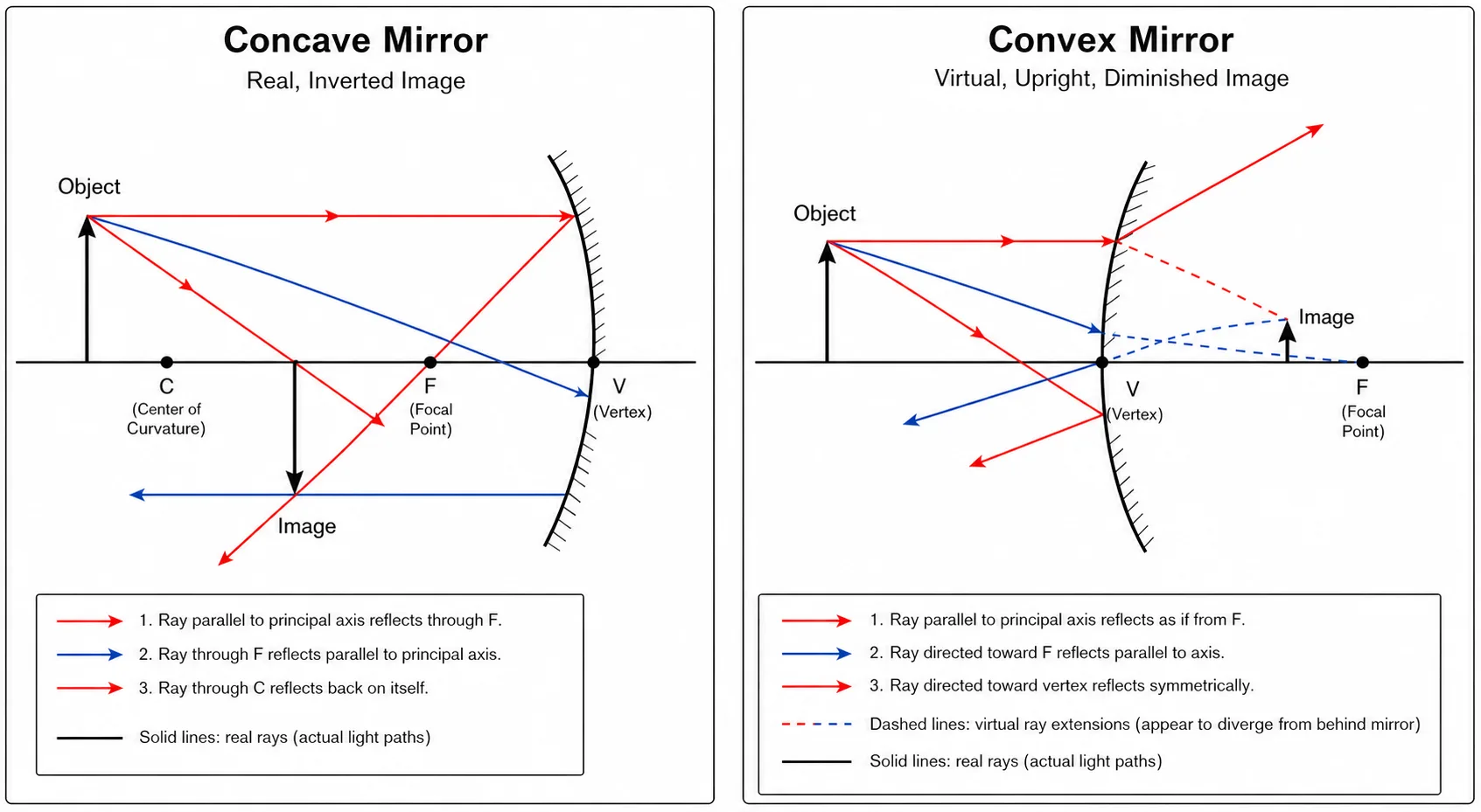
For curved mirrors, three principal rays are used:
- A ray travelling parallel to the principal axis reflects back through the focal point F.
- A ray passing through F reflects back parallel to the principal axis.
- A ray heading toward the centre of curvature C strikes the mirror head-on and reflects straight back on itself.
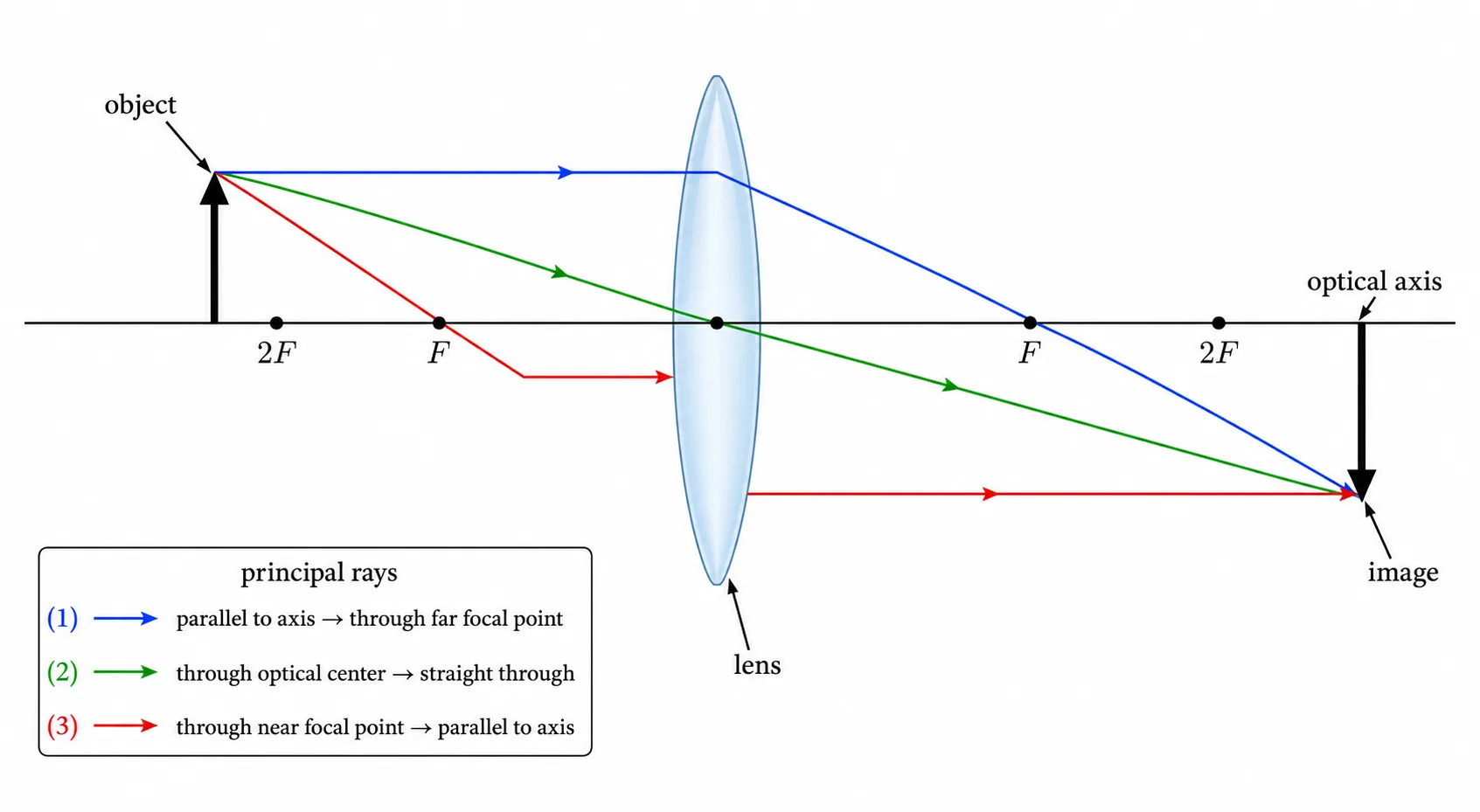
For thin lenses, the three principal rays are:
- A ray parallel to the axis refracts so that it passes through the focal point on the far side.
- A ray through the optical centre of the lens passes straight through, undeviated.
- A ray through the near focal point emerges parallel to the axis.
You only need any two of these to locate the image; the third confirms your construction. Where the rays intersect, the image forms. If they diverge instead, extend them backward to find a virtual image.
The concave mirror ray diagram
A concave (converging) mirror curves inward toward the object, so it brings parallel light together at the focal point. What kind of image it forms depends entirely on where the object sits:
- Beyond C: real, inverted, and diminished.
- At C: real, inverted, and the same size as the object.
- Between C and F: real, inverted, and magnified.
- At F: the reflected rays come out parallel, so no image forms (it is said to be "at infinity").
- Inside F: virtual, upright, and magnified — the principle behind a shaving or makeup mirror.
To draw it, place the object as an arrow on the axis, send out the parallel ray and the focal ray from the tip, and mark where they meet. That intersection is the tip of the image.
The convex mirror ray diagram
A convex (diverging) mirror bulges toward the object and spreads reflected rays apart. Its focal point sits behind the mirror, so the reflected rays never actually cross. Extending them backward shows the image always forms behind the mirror.
Because of this, a convex mirror ray diagram has a reassuringly simple result: the image is always virtual, upright, and diminished, no matter where the object is placed. As the object moves closer the image grows slightly, but it never becomes larger than the object and never turns real. This wide, shrunk-down field of view is exactly why convex mirrors are used as car wing mirrors and store security mirrors.
The converging lens ray diagram
A converging (convex) lens refracts parallel rays to a focal point on the far side. Like the concave mirror, the image it forms depends on object distance:
- Beyond 2F: real, inverted, and diminished.
- At 2F: real, inverted, and the same size.
- Between F and 2F: real, inverted, and magnified — the projector and camera regime.
- At F: rays emerge parallel and no image forms.
- Inside F: virtual, upright, and magnified — the lens is acting as a simple magnifying glass.
The standard construction sends one ray in parallel to the axis (refracting through the far focal point) and one straight through the optical centre; their crossing point is the image.
The diverging lens ray diagram
A diverging (concave) lens spreads parallel rays apart, as if they came from a focal point on the same side as the object. As with the convex mirror, the outgoing rays never meet, so you trace their backward extensions.
The result is just as tidy: a diverging lens ray diagram always gives a virtual, upright, diminished image, located between the lens and its focal point, whatever the object distance. This is why diverging lenses are used to correct short-sightedness and to widen fields of view.
Combining elements: instruments
Once you can draw a single mirror or lens, you can analyse instruments that stack them. A compound microscope ray diagram chains two converging lenses: the objective forms a real, magnified image, which the eyepiece then magnifies again as a virtual image. A telescope ray diagram does something similar for distant objects, with a large objective gathering light and an eyepiece producing the final enlarged view. The same principal-ray rules apply at each element in turn — you simply treat the image from the first element as the object for the next.
Why ray diagrams matter
Ray diagrams turn an abstract optics problem into something you can see. Before reaching for the mirror equation, 1/do + 1/di = 1/f, or the thin lens equation, 1/f = 1/do + 1/di, a quick sketch tells you what kind of answer to expect: whether the image should be real or virtual, which side it lands on, and roughly how large it is. That intuition catches sign-convention slips and arithmetic errors before they happen, which is why exam questions so often ask you to draw the diagram first and calculate second.
How to read and draw a ray diagram
A reliable routine works for every case:
- Draw the principal axis and the element, and mark F (and C for mirrors) to scale on both sides.
- Draw the object as an arrow standing on the axis at its given distance.
- From the tip of the object, draw two principal rays following the rules above.
- Mark where the rays cross — that is the tip of the image. If they diverge, extend them backward (dashed) to find a virtual image.
- Read off the three properties: real or virtual, upright or inverted, magnified or diminished.
Drawing carefully to scale is the difference between a diagram that merely looks right and one that actually predicts the image distance. If you want clean, correctly proportioned diagrams without fighting with a ruler, you can generate one directly from your setup.
Common mistakes
- Confusing convex and concave behaviour. A concave mirror and a convex lens both converge light; a convex mirror and a concave lens both diverge it. Match the behaviour, not just the word.
- Forgetting to extend rays for virtual images. When rays diverge, the image is found by their backward extensions, drawn as dashed lines — never where the solid rays end.
- Misplacing F and C. For a mirror, the centre of curvature is twice as far out as the focal point; getting this ratio wrong distorts the whole construction.
- Drawing freehand and off-scale. Two rays that are slightly off will still cross somewhere, giving a confident but wrong image. Use a scale.
- Expecting a real image from a single diverging element. Convex mirrors and diverging lenses can only ever produce virtual, upright, diminished images on their own.
Frequently Asked Questions
- What is a ray diagram used for?
- It locates the image formed by a mirror or lens and describes it — real or virtual, upright or inverted, magnified or diminished — by tracing a few principal rays, without solving equations first.
- How many rays do you need to draw?
- Two principal rays are enough to fix the image point; a third is drawn as a check. All rays from one object point converge at the same image point.
- What is the difference between a real and a virtual image?
- A real image forms where light rays actually cross and can be projected on a screen (and is inverted). A virtual image forms where rays only appear to come from, cannot be projected, and is upright.
- Why is a convex mirror image always virtual?
- A convex mirror diverges reflected rays, so they never cross in front of it. Their backward extensions meet behind the mirror, producing an image that is always virtual, upright, and diminished.
- When does a converging lens make a virtual image?
- Only when the object is closer than the focal length. Inside F, a converging lens acts as a magnifying glass, giving a virtual, upright, magnified image; beyond F it produces real, inverted images.